TAC2 – Trajectory and Catch
Introduction
 The TAC2 code can be used to calculate the trajectory of cloud water droplets and resultant water droplet catch efficiency distribution on a multi-element 2D body in incompressible flow. The code is design software for providing advice on the susceptibility of a surface to impact by cloud water droplets. It can be used to establish the amount and location of water droplet impact on a body, which is a pre-curser to the calculation of ice accretion shape and size, and in the modelling of ice protection systems.
Technical
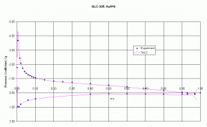
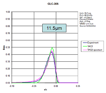
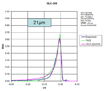
The code uses a Lagrangian particle tracking technique to calculate the trajectory of a cloud water droplet from a starting position upstream of the aerofoil under investigation. The position of the droplet is integrated in small steps until either the droplet impacts the aerofoil or it passes defined boundaries (used to signify a ‘miss’ trajectory). A fourth order Runge-Kutta technique is used to integrate the equations of motion, which assume only aerodynamic drag affects the droplet motion. The integration requires the local velocity components to be known at every position the droplet occupies. In the TAC code, the required velocity data are calculated using a 2D, multi-element, incompressible flow, panel method which is based on linear varying vorticity on each panel. The code calculates the limiting trajectory (i.e. tangential to the aerofoil surface) on each of the upper and lower surfaces on a user specified number of the aerofoil components. A user specified number of ‘intermediate’ trajectories in between these limits is then evaluated. A cubic spline fit is made to the initial point (‘Y0’) and impact point (‘s/c’), with a zero gradient end slope condition applied at the limiting trajectory points. The slope of the cubic spline is then evaluated at a series of points about the aerofoil leading edge, which corresponds to the local water droplet catch efficiency, β. The code also calculates the ‘overall’ catch efficiency, E, which is expressed as the separation between the two limiting trajectories in the free stream relative to the projected height of the aerofoil. Finally, using the panel method calculated surface velocity data, the code conducts an integral boundary layer calculation for a rough surface to predict the local surface convective heat transfer coefficient distribution, which is output, along with pressure coefficient and catch distribution, in the format required by AID modules IHB and ET3D.
TAC2 can automatically calculate the catch efficiency for a spectrum of droplet sizes (e.g. for a Langmuir-D distribution). Trajectories on a 3-element aerofoil


